Wednesday 22 November 2017

Like a Boss

Now there's a title: A bold running start, a title fit for an epic post. A title full of optimism and hope. A title spoiled only by the quality of what follows. You see, I've spent much of the last few weeks engaged in one form of development related navel gazing or another. Please allow me to explain...

Filthy OSes


I do all my hobby stuff on an ageing Tecra laptop. It's now over 10 years old, but I've no reason to change it as it works fine and has respectable performance. The only problem is Windows XP, which is way past its end of support. It ran off the top of that particular cliff three years ago, and very much like Wile E. Coyote, is kind of just hanging there waiting for gravity to notice. Updates for various bits of software are drying up, it's increasingly likely I have to search for old versions of drivers, and the nagware anti-virus software is a big resource hog. We hates it.

I briefly looked into upgrading to Windows 7, but Mister "None Shall Pass" Upgrade Advisor Wizard flagged up a bunch of issues with the hardware. Scratch that idea: Time to look at a free OS.

I've played with a Linux distro before. I must have been feeling particularly wealthy circa year 2000, because I walked into a PC shop and bought a boxed SuSE Linux 6.2 or 6.3 to see what all the fuss was about. I've still got the box in the roof somewhere. Anyway, I installed it on a 486 PC and it worked well enough, but I didn't really do anything with it due to lack of software that could work with the stuff I'd been doing on Windows. I lost interest and stopped using it. That was a mistake with a capital M. I've basically missed out on over 15 years of useful education.

Like I GNU you would


I guess I've got a bit of catching up to do then. Now the thing that rapidly becomes apparent is the amount of choice available for a free OS: There's a bewildering selection of distributions, kernels, and desktop managers to choose from. If your worst nightmare is based around having to make a decision then this might not be your night. To help me decide I came up with the following sketchy criteria: 'Popular', 'Lightweight' and 'Googled evidence that it works on an old Tecra'. To cut a long story short I eventually settled on Debian/Linux with an Xfce desktop.

It almost worked first time: I had to download a legacy driver to get the wifi working and the trackpad settings needed a tweak but I was very impressed at how smoothly it all went. So now game development is proceeding on *nix. If I can stop playing 2048, that is...

So, Anyway


In spite of all that I did manage get some work done on the game.

In Time Pilot '84, a boss appears after a certain number of enemy craft have been destroyed. The boss chases after the player while continuously firing homing missiles. To defeat the boss and proceed to the next level, the player must wait to acquire a missile lock and then successfully fire a missile while avoiding collision with the boss or its missiles.

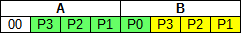
The boss is quite large compared to the player, and rather than write a special large sprite routine, I chose to construct it out of four standard sprites effectively flying in tight formation.

I see five sprites

To get the boss to chase the player we need to figure out how to determine the direction of the player relative to the boss. Those who know their vectors will know that subtracting the boss coords from the player coords will give the precise direction of the player, though it would be hard to make use of it as we would need to convert that direction into a unit vector which means square roots and stuff.

More useful would be a function that returned an angle. That would allow us to steer the boss towards the player. One way to get an angle from vector components would be to use the arctangent function, but that's no better than having to calculate square roots, which leaves us wondering if there is some approximation we can use.

Mmm pie


It turns out there is something relatively simple we can do. If you imagine a cherry pie centred on the boss, and that pie is divided into four delicious slices, aka quadrants, then it's easy to figure out which quadrant the player is in just by looking at whether the difference in coord components is positive or negative. Even better, it's possible to refine it more and divide the area into eight octants by comparing the sizes of the x and y components. (And a thinner pie slice means you can have a bigger blob of double cream. Ooh you would)

The following piece of code returns an octant number in the range 0-7 based on the difference in coords. It works by progressively rotating the coords until they lie in the first quadrant then finally comparing the x and y components to figure out which octant:

        clrb         ;
        lda dy       ;
        bpl ypos     ; dy >= 0
        neg dx       ; rotate 180 cw
        neg dy       ;
        addb #4      ;
ypos    lda dx       ;
        bpl xpos     ; dx >= 0
        nega         ; rotate 90 cw
        ldx dy       ; don't care about low byte
        stx dx       ;  just need to swap dx & dy
        sta dy       ;
        lda dx       ;
        addb #2      ;
xpos    cmpa dy      ;
        bhs done     ; dx >= dy
        addb #1      ;

done                 ;


The coords have previously been scaled and subtracted and stored as 8 bit values in dx & dy. In case you're wondering what the strange business with ldx/stx is about, it's because at that point I need to keep the contents of both the A and B registers and rather than save and restore one of them, I used the X register and saved a few bytes and cycles instead. stx dx overwrites dy, but it doesn't matter because we then write to dy in the next instruction.

The number returned in B represents the direction in which we want the boss to move, and that can be used to look up a velocity from a table. Now, rather than suddenly change to the new direction like Automan's car, I increment or decrement the current direction once per update so that the boss steers more gently towards the player. But even that is too aggressive: The boss homes in on the player far too efficiently and there is no way to avoid the collision. (It does work great for homing missiles however.)

That left me wondering how the original arcade game worked as I remember it being pretty easy to avoid a collision. I tried slowing the boss down as it approached the player and slowing down the update rate but nothing seemed to give a satisfactory result.

In the end, I fed a fraction of the player steering input into the homing routine. What now happens is the boss approaches the player while the player is flying in a straight line, but if the player turns, the boss steers behind the player. Rather surprisingly this ad hoc solution feels more true to the original.

Out with a bang


For a while I wasn't sure what should happen when the player defeats the boss. I didn't think I would be able to pull off a convincing explosion, so I decided to cheat instead. When the player successfully hits the boss, a mode change occurs and the boss starts running away from the player while pouring out flames, which are just re-used enemy explosion graphics. Here's how it looks so far:


The battle is a bit one-sided at the moment. The boss still needs to fire missiles at the player, and the player should have to sweat it out for a while before getting a missile lock, but it's a good start.

I'm in two minds what to do next: I could finish the boss battle or I could try out some musical ideas while they're still fresh in my mind. Also December is almost upon us. So much to do, so little time...

Thursday 5 October 2017

Sounds Like a Plan

Sounds like a pain?


I was nervous about the sound effects, having found it in the past to be hard work to get good results. The Dragon and CoCo machines have a 6 bit DAC that is capable of creating some fantastic sounds, but in a rather cruel twist, things are not easy if you want sound at the same time as animation.

The problem is that sound generation requires a fairly regular rate of writes to the DAC, whereas updating graphics often involves a variety of routines of different lengths. The two things don't mesh together very well, so what usually happens is that the sound ends up being produced in short bursts in between screen updates, creating a distinctive thin and choppy kind of sound that can be heard in many Dragon and CoCo games.

Trip down memory lane


In my first game, Balldozer, there wasn't much work to do to keep the graphics updated: Just a ball, a bat and a power-up, along with the occasional brick that needed erasing. That allowed me to have relatively long bursts of sound in between the updates. Low frequencies with decaying volume were generated when the ball bounced off the bat or the sides of the screen, giving a 'boing' sound, and higher frequencies were generated on hitting the bricks, giving a 'ching' sound. This worked out pretty well:


For my second game, ROTABB, I didn't put any sound in until the last minute and it really shows. Because the sound in Balldozer worked out OK, it didn't occur to me that I would have a problem. What I discovered too late was there were no spare cycles left over, and the best sound I could achieve during normal play were some feeble explosions for destroyed enemies. The only way I could find to generate a reasonable sound effect was by having longer bursts of sound and letting the frame rate drop. So to avoid messing up the gameplay, I only did this for destroying the level boss and for the player death, where the lower frame rate gives a nice slow-motion effect. The lesson here is to allow for sound early on in the design:


For the abandoned third game, I had started experimenting with producing sound and graphics at the same time i.e. embedding the DAC update code within the graphics update code. This game spent a lot of time drawing background tiles, so I inserted a DAC write for every second tile drawn. The values to write to the DAC were read from tables, with the volume of the sound being set by a MUL instruction. This gave a much more full and satisfying sound:


Back to the Future


For the new game I would like the sounds to have something of an arcade feel. That generally means lots of noise going on, with a variety of sounds that are rich in low to mid-range frequencies. I felt that the sound in the third game was a step in the right direction, so I decided to build on those ideas:

  • Embed more DAC updates in the game code
  • Make the DAC updates more efficient by not using MUL for volume
  • Instead of a set of fixed wave tables, have a sound buffer that is updated by the sound engine at the start of each game loop
  • Sound engine that generates sounds from parameters
  • Choose a sound effect for playback by pointing to a parameter entry in a table

This list is saying I need a sound engine that is much more sophisticated than anything I've done before. Fortunately the task can be broken down into more manageable pieces. First of all I need a small piece of code that takes one sample from the buffer, writes it to the DAC and updates the buffer pointer using a minimum of registers so that it can be embedded in existing code without causing too much upheaval:

    lda [sndbufptr] ; Get next sample
    sta $ff20       ; Write it to the DAC
    inc sndbufptr+1 ; Update buffer pointer


That takes 20 cycles. It can be reduced slightly by using self-modifying code, but that's only worth doing in a loop with a fair number of iterations because of the overhead of copying the buffer pointer at the start and end. Note that I'm only incrementing the bottom byte of the buffer pointer. This is fine providing the buffer is completely contained within one 256 byte page.

So how many DAC updates do we need to embed in the game loop? Say we wanted an update rate of 1KHz. Assuming normal CPU speed and a frame rate of 25fps, that means an update approximately every 895 cycles, or 40 updates per game loop.

Those updates need to be sprinkled as evenly as possible throughout the code. This is not an easy thing to do, but it doesn't need to be perfect and it might be easier to change the update rate to suit the code. For example I've put a DAC update inside the loop that copies 128 byte blocks of background to the screen. That performs 21 updates spaced at 523 cycle intervals, forcing me to aim for a higher update rate of 1.7KHz

In the tile drawing routines, the loops are slightly too short, so the DAC update is preceded by a flag toggle to perform the update every second loop.

If a loop is really short, then it might be necessary to break the loop up into two or more chunks by having an inner loop doing the work and an outer loop containing the DAC updates. It's a similar story for the loop that waits for the video frame sync. I have an inner loop checking for the sync flag in the PIA, and the outer loop performs the DAC updates at the target rate.

Where's that noise coming from?


Next we need to generate some data to put into the sound buffer. To keep things simple I decided to have a single sound channel. This means only one sound effect plays at a time, and a priority system is required to prevent a less important sound from interrupting a more important sound.

There are two types of sound commonly generated by sound chips, namely square wave and noise, so we may as well start with those. The following code writes a square wave* to the buffer with adjustable frequency and volume:

snd_square
      ldx #soundbuf
      ldb snd_phase
      lda snd_vol
ssqlp sta ,x+
      addb snd_freq
      bcc ssq1
      eora snd_vol
ssq1  cmpx #soundbuf_end
      blo ssqlp
      bra donesound


The frequency and volume are values in the range 0-255. The higher they are, the higher the frequency and volume respectively. snd_phase stores the value of the B register between successive calls to the routine, so that the square wave continues where it left off on the previous game loop. (Though the placement of DAC updates would have to be very accurate for this to make much difference, and if I did get that accurate, I would have to save the volume of the square wave between calls as well)

The noise routine is a little more complex. It reads values from a table of random numbers, sets the volume by ANDing with a mask and then outputs the values to the buffer. The values are repeated in a similar way to the square waves to give some control over the frequency content of the sound. I've used self-modifying code so that the routine is not too slow compared to the square wave routine:

snd_noise
      ldx #soundbuf
      ldu #rndtable
      ldd snd_vol   ; snd_vol & snd_freq
      sta sns2+1    ; volume
      stb sns3+1    ; frequency
      ldb snd_phase
      anda ,u+      ; first sample
snslp sta ,x+
sns3  addb #0       ; frequency
      bcc sns1
      lda ,u+       ; get next random value
sns2  anda #0       ; set volume
sns1  cmpx #soundbuf_end
      blo snslp
      bra donesound


The random number table is a 64 byte table of pseudo-random values, refreshed at a rate of one new byte per game loop such that the table contents are continuously changing.

Now we need a table to define the different sound effects. Each table entry defines the type of sound, how long it lasts and how it changes over time. That suggests these parameters:

  • Sound duration
  • Start volume
  • Change in volume per game loop
  • Start frequency
  • Change in frequency per game loop
  • Address of sound generator (square or noise)

The good news is those parameters fit into seven bytes, meaning we can pack a lot of different sound effects into a small space.

When a sound effect starts, the volume and frequency are copied to variables for the sound generator to use. Then for each game loop, the sound generator is called and then the volume and frequency have the 'change' parameters added to them. The duration is used to initialise a counter that is decremented once per game loop to set the length of the sound.

The sound priority is defined very simply by the address of the parameters. Sounds nearer to the start of the table have lower priorities than sounds nearer to the end of the table. When a sound effect request is made, the address of the new sound is compared to the address of the current sound. If the new address is lower, then the sound is not started, otherwise the new sound will replace the existing sound.

If the current sound has address zero, then it means no sound is playing, which happens when the sound duration counter has expired, for example. Having the lowest possible address also means the silent state has the lowest priority, ensuring the next sound request will be granted.

Put it all together and what do you get?


I've implemented the ideas discussed but haven't to date put a lot of effort into spreading out the DAC updates evenly. There are about 44 DAC writes per loop, some bunched up, some spread out and a big gap when the sprites are being drawn. Even so, the result is surprisingly good: (Please excuse the jumpy video. The game runs much more smoothly than this)


Back to the Future II


At some point I would like to add more parameters to make the sound effects more complex, such as periodic frequency variation (vibrato) and variable duty cycle for the square waves. I also need to do a better job of spreading out the DAC updates plus there is the issue of supporting both PAL and NTSC machines, as the different frame rates mean different sizes of sound buffer. But on the whole I am extremely pleased with the new sound engine. I just wish I had thought of it back in the day :)

As a final thought it occurred to me that the same sound engine could be used to drive a variety of different sound hardware (such as sound carts) just by replacing the lowest levels of the driver. Definitely worth considering for a future 'deluxe' version.

I'd better get on and write some more code before I run out of things to write about...


*Caution: Under no circumstances attempt to generate square waves in real life. The infinite accelerations and energy densities required would rapidly bring on the end of the universe and possibly void the warranty on your speakers.

Tuesday 5 September 2017

Crash Course

Ooh it's a good one this time: They're doing collision detection.


Call me old fashioned...


...but I like stuff to blow up when I shoot at it. There are some enemy sprites flying around, some player bullets headed in their general direction and I'd like to know when a bullet hits a sprite so I can make it asplode.

One way is by comparing the coordinates. If you imagine subtracting the coords of one object from another, then the result will say something about how close together those objects are. Small numbers = close together, big numbers = far apart.

In fact we can tell if two rectangular regions are overlapping by subtracting the coordinates and comparing the resulting numbers against limits:

    ldd XORD,y
    subd XORD,u
    cmpd #high_limit_x
    bgt miss
    cmpd #low_limit_x
    blt miss
    ldd YORD,y
    subd YORD,u
    cmpd #high_limit_y
    bgt miss
    cmpd #low_limit_y
    blt miss
    ; Hit. You sunk my battleship.

That takes about 56 cycles. It can be reduced to 52 cycles by noting that each cmpd # can be replaced with a faster subd # and modifying the limits. (Also handy to know is that cmp #value can be replaced with add #-value, which allows you, for example, to compare against positive and negative versions of the same variable)

More cycles than Halfords


Now, here's the thing: We need to check each object against every other object with which we wish to detect a collision.

Taking the case of eight player bullets and eight enemy sprites, that makes 8 x 8 = 64 collision checks. At 52 cycles per check that amounts to well over 3ms. Ouch. That's 10% of the total time budget, or a very large chunk of the time remaining after the background and sprites have been drawn. And I still have to detect collisions with the player and implement sound.

I did some research on optimising collision detection, using space partitioning methods such as quadtrees, but soon began to realise that these techniques are better suited for more powerful systems dealing with larger numbers of objects. Not only that, the worst case scenario would still require the maximum number of checks, resulting in dropped frames and slow downs. Suddenly the performance of my game wasn't looking so good. Reality had invited itself round for dinner, like some kind of unwelcome freeloading walrus, and there was nothing I could do about it, except perhaps to hide in a cupboard until the problem went away.

But then I started to think about how collision detection was often done in games written in BASIC. For example in text mode games, before an object is drawn, the destination address can be checked to see what's already there. Or in graphics modes, PPOINT was often used to check the colour of a target pixel. Both amount to the same thing: Using the data in the screen buffer to detect collisions.

One of these pixels is not like the others


So the new strategy could work like this: The routine that draws the bullets records data for each bullet location. Then, after each sprite is drawn, the data is compared against the new screen contents. If something is different then we know that the sprite just drawn has been hit by the bullet just checked.

Because the bullets are only one pixel in size, we just need to record one pixel of information for each. The information is comprised of address, mask and pixel value. The address tells us where in the buffer the bullet is drawn, the mask selects the pixel of interest (out of the four pixels making up a byte), and the pixel value is the bullet colour ANDed with the mask, giving us something we can use to detect changes.

After each sprite is drawn, it will need to check for all eight bullets, using something like the following bit of code repeated eight times:

    lda addr1  ; grab data from screen
    anda mask1 ; select pixel of interest
    cmpa pix1  ; compare with bullet colour
    bne hit    ; collision if not equal

As this code fragment could be run 64 times, every single cycle matters, so I've opted to use self-modifying code, with the bullet update routine storing the data directly into the collision detect code:

addr1 lda >0   ; 5 cycles
mask1 anda #0  ; 2
pix1  cmpa #0  ; 2
      bne hit  ; 3

We're now down to 12 cycles per check, which when added to the additional code in the bullet update routine, takes less than a third of the time taken by the coord comparison method. Much better!

Now I should mention that this method does have a flaw: If the sprite pixel is the same colour as the bullet pixel then the collision won't be detected. It's not as bad as it sounds, because there is a good chance that a missed collision will be picked up on the next frame when the bullet moves to a different part of the sprite. Consider also that the coord comparison method is not perfect either, and requires the collision region to be a rectangular approximation of the true shape of the sprite image. On balance I think the faster method easily wins.

Incoming


That leaves us with detecting collisions with the player. The coord comparison method could be viable here, because we only need one check per enemy sprite. The downside is that the accuracy will be a compromise. To avoid unfair situations, the bounding rectangles will have to be completely contained within the sprite images, which could mean large parts of sprites overlapping without a collision being detected. Instead, a more accurate screen buffer method could be used:

  • First draw the player
  • Then draw all the sprites that are dangerous to the player
  • Then check the screen buffer to see if anything has been drawn on top of the player

To determine if anything has been drawn on top of the player, we can use the player mask data to extract a player-shaped region of the screen. This should be identical to the player image, otherwise something must have been drawn on top. The following bit of code does just that:


loop  pulu d     ; get two mask bytes
      coma       ; invert mask bytes
      comb       ;
      anda ,x    ; collect data from mask-
      andb 1,x   ; -shaped region of screen
      subd ofs,u ; compare with image data
      bne hit    ; difference means collision
      pulu d     ; get next two mask bytes
      coma       ; and do same again
      comb       ;
      anda 2,x   ;
      andb 3,x   ;
      subd ofs,u ;
      bne hit    ;
      leax 64,x  ; check every other row
      leau 4,u   ;
      dec count  ;
      bne loop   ; repeat until done

u is pointing to the player mask and image data, with ofs being the size of the mask data minus two, to allow for pulu d adding two. x is pointing to the screen buffer. Note that I'm testing every other row to save time, the assumption being that this is sufficient to detect a collision with a large object. If I needed to detect collisions with single pixels then I may have to check every row.

This routine takes about 500 cycles to check six rows of player sprite, which is actually a little slower than comparing coords, but has the advantage of greater accuracy. It could be accelerated by using a compiled sprite technique, unrolling and converting instructions to immediate mode, but it would consume a lot of memory, requiring one routine for each of the 16 player directions. Worth keeping in mind for a high-performance 64K version.

Another advantage over coord comparisons is that the run time is independent of the number of objects. I could decide to add a load of enemy bullets for example and the player collision check would take the same amount of time.

The downside is that we don't know which object collided with the player. This is OK for my purposes, but might not be enough for some games. One way to work out which object was in collision would be additional code after the screen buffer test to determine which object was nearest to the player. (Though be careful of situations where the nearest object may not actually be the one colliding with the player)

He's making a list


These collision detection methods require the sprites to be handled in different ways. There are collidable sprites, such as enemies, that need to be checked for collisions, and there are non-collidable sprites, such as explosions, which skip the checks. These are allocated from a pool of eight free sprites.

And checking it twice


I have implemented three linked lists, to keep track of the collidable, non-collidable and free sprites. The non-collidable sprites are drawn before the player and skip the player bullet checks. The collidable sprites are drawn after the player and before the player collision check and have the bullet checks enabled. (Drawing the non-collidable sprites before the player avoids drawing the same sprite twice in one frame as would happen when an enemy sprite is turned into an explosion.)

Oh crap it's almost Christmas


I'm using one-way linked lists to keep the overhead down (each list item having a pointer to the next list item), and this is working OK, but I'm not sure if that will be the solution used in the final version of the game. Moving an item from the collidable to the non-collidable list takes six load/stores to modify the pointers leaving me wondering if there's a better way. Perhaps a job for another time...

Saturday 29 July 2017

Sprites

I might be slow, but at least I'm inconsistent. A few weeks ago, I thought, "I know, I'll read Stephen King's Dark Tower novels again, seeing as I'm a bit of a fan and the movie is coming out soon. It won't take long; There are only eight books, and probably not much more than 4000 pages." The next thing I'm aware of is struggling to remember the password to get back into this blog.

In the meantime, Ciaran Anscomb has been working hard and has got his excellent Dunjunz conversion ready for release. This is an achievement to be proud of as finishing a project can sometimes be the hardest part. Check it out; it's everything a game should be.

Right, I can't put it off any longer. Strap in and prepare yourselves for some awful puns. Truly awful.


Let there be sprite


As this is a shoot-em-up, we need cannon fodder to shoot at, enemies flying around and suchlike, and for that we will need some sprites.

I'm not sure of a precise definition for a sprite, but perhaps a reasonable description would be a graphical object that moves around separately to the background. It's a bit like a tile, but with a life of its own and behaviour that depends on what type of object is being represented.

This suggests that a sprite should have variable and constant data associated with it in addition to the image data. For example I've currently got the following pieces of information making up a sprite:

  • Pointer to image data
  • Screen coordinates
  • Velocity
  • Scoring and sound effect information
  • Pointers to routines that implement behaviour

The image data pointer can be constant or changed frame by frame to give animation. There are more than a few ways of drawing sprites, each with a different trade-off between memory use and speed. I would like to draw at arbitrary pixel coordinates which means bit shifting will be involved. At the slow end of the spectrum we could pixel shift the image data as it's being drawn, or at the fast end we could have pre-compiled sprites, where the image data is embedded into immediate instructions.

I've opted for a middle-of-the-road method that is based on pre-shifted image data. By that I mean the four possible bit-shifted versions of the image already exist in memory at the time of drawing.

I've chosen a sprite size of 12 x 12 pixels, requiring 3 x 12 = 36 bytes per image. When converted to the pre-shifted form, it takes 48 x 4 = 192 bytes, because an extra byte of width is needed to fit a shifted image, and we need four images, each with a different amount of shift. The extra memory used is the price paid to gain some speed.

Simply copying the sprite data onto the screen isn't going to work very well in this game, because the background would be overwritten by the parts of the sprite image that should have remained transparent. A way to fix this is to use a mask i.e. an image that is ANDed onto the screen to make a hole into which we can OR the sprite image.

A set of pre-shifted masks and images

Unfortunately, using logical operations means we are restricted to using the a and b registers to transfer the image data to the screen, though a small optimisation is to use ADD instead of OR, allowing us to combine two 8 bit operations into one 16 bit operation. Drawing one row of sprite looks a bit like this:

    pulu d     ; get two bytes of mask
    anda ,x    ; AND with screen
    andb 1,x   ;
    addd 46,u  ; OR with two bytes of image data
    std ,x     ; store onto screen
    pulu d     ; get next two bytes of mask
    anda 2,x   ; etc
    andb 3,x
    addd 46,u
    std 2,x
    leax 32,x  ; move to next screen row

The u register is pointing to the image data which is made up of 48 bytes of mask followed by 48 bytes of sprite. x is pointing to where we need to draw in the screen buffer. Nothing too exciting going on, but it gets the job done.

Sprite place at the sprite time


To determine where to draw the sprite, we need to calculate a screen buffer address from the coordinates. To simplify the address calculation, I'm using scaled coordinates. The x-coord is scaled by 64 and the y-coord is scaled by 32. That means I can form an address just by throwing away the bottom five bits of the y-coord, adding the top byte of the x-coord, then adding the screen buffer base address:

    ldd SP_YORD,y  ; y part of coord
    andb #$e0      ; remove sub-pixel bits
    adda td_fbuf   ; screen start address
    tfr d,x
    lda SP_XORD,y  ; x part of coord
    leax a,x


The y register is pointing to the sprite variables and the calculated address is returned in x. Note that I'm only adding the top eight bits of the buffer base address. This is fine as long as the bottom eight bits are zero.

That gives us the address, but we also need to select one of the pre-shifted frames to show the sprite in the correct pixel column. We need to determine the shift value 0-3 and then multiply that by 96 to give us an offset to add to the sprite image address.

Noting that the shift value is contained in bits six and seven of the x-coord, i.e. already multiplied by 64, we can get the required result by multiplying those bits by 1.5 (Because 64 x 1.5 = 96):

    ldb SP_XORD+1,y
    andb #192
    clra
    leau d,u
    lsrb
    leau b,u


Having to use clra and leau d,u is a bit unfortunate and is there to avoid interpreting the top bit of b as a sign bit. One day I may look into re-arranging the pre-shifted data and replace the last four instructions with the more efficient:

    leau b,u
    asrb
    leau b,u

Or even better, if the registers can be re-allocated without incurring a penalty somewhere else:

    abx
    lsrb
    abx

The speed of sprite


Movement is achieved very simply by regularly adding a velocity to the coordinates. The moving background makes things slightly more interesting because we want to specify the sprite velocity relative to the background, not the screen. The way to deal with that is to add the background velocity to the sprite velocity. The background velocity is determined once per frame and affects all moving objects equally. The coord update looks like this:

    ldd SP_XORD,y   ; horizontal component
    addd SP_XVEL,y  ; sprite horizontal velocity
    addd scroll_x   ; background horizontal velocity
    std SP_XORD,y

    ldd SP_YORD,y   ; vertical component
    addd SP_YVEL,y  ; sprite vertical velocity
    addd scroll_y   ; background vertical velocity
    std SP_YORD,y

A Hard Day's Sprite


I'd imagine that most people who have experimented with software sprites will have seen what happens when a sprite goes off the edge of the screen. Going off the left or right edges usually means harmlessly reappearing on the other side, but going off the top or bottom can spell disaster as the sprite has moved out of display memory and possibly into memory being used for something else. It's something to be avoided.

In some games the issue can be avoided by ensuring the sprite coords always remain within bounds. However, in my game I would like sprites to cross the screen edges, moving in and out of view just as the background does. That means the sprites must be clipped at the screen edges.

In ROTABB, I had a screen buffer that was larger than the viewport. The sprites were rendered into the buffer and then the central portion of the buffer was copied to the screen, automatically clipping any sprites overlapping the edges of the viewport. Unfortunately, that doesn't sit very well with my new scrolling engine which relies on being able to copy big chunks of data without worrying about where the screen edges are. Plus I need to at least try to keep memory use down, meaning the buffers should be no larger than necessary. I'm going to have to clip sprites the hard way.

Clipping at the bottom of the screen isn't too bad. If the y-coord is greater than the screen height less the sprite height, then the sprite needs to be partially drawn. Subtracting the y-coord from the screen height in fact gives us the number of sprite rows to draw. If it's zero or negative then the sprite is completely off screen and doesn't need drawing.

Clipping at the top is a little more complicated in that we need to calculate how many rows to draw and we also need to calculate an offset for the image data, because the drawing no longer starts at the top row of the sprite. If the y-coord is negative then we need to clip. If it is less than or equal to the negated sprite height then the sprite is off screen. Negating the y-coord tells us how many rows of image to skip, and subtracting that value from the sprite height tells us how many rows to draw.

Sprite of hand


Clipping at the left and right edges is something altogether different. We need to selectively draw one, two, three or four bytes wide, depending on how much of the sprite is visible. I'm happy to say that Steve Bamford had already figured this one out and shared his clever solution involving a lookup table. All we need to do is take the horizontal offset of the screen address and use this to look up the address of a sprite drawing routine from a table. (Taking care to treat the offset as a signed value, because it becomes negative as the sprite crosses the left edge.)

The different sprite routines look after drawing the different widths of sprite and not a single x-coord comparison is required, because the lookup table can be book-ended with addresses that point to a routine that deals with the sprite moving completely off screen. Very elegant. Thanks, Steve!


A sprite for sore eyes:
Clipping in action on all four sides of the screen

Sprite at the end of the tunnel


I've got some more distractions coming up in August but hopefully it won't be too long until the next post, even though the path of the spriteous man is beset on all sides by the inequities of life and the tyranny of work. Or something.

Friday 16 June 2017

Every which way

It's been a while, lots of distractions, such as decorating, family time, Season three of Better Call Saul, and preparing for the Cambridge Dragon Meetup, which was a lot of fun and hopefully will become a regular event. It was really good to meet the people I'd been chatting to and following these last few years.

It was also great to see other work in progress games at the show. In fact showing me how it's done properly. There was Steve Bamford's Circe's Island, with stunning Nintendo-esque graphics and sophisticated gameplay, and Ciaran Anscomb's Dunjunz, a brilliant reconstruction of an 80's game dripping with 8-bit goodness.

Why I oughta


In other news, I got trolled by my seven year old son. He got me good...

I was recently trying to diagnose a problem with one of my Dragons, where it would intermittently fail on startup, or crash after a short time. After poking it with a stick for a while, I decided the problem was due to the CPU not being connected to the rest of the computer, or "dry joints" as the condition is sometimes known.

A little bit of soldering later, the machine started looking like it was going to behave itself, so I let my son Ed have a play to give it a test. I showed him how to assign values to numeric and string variables, perform some simple operations, and print the results.

After a while, a voice calls down the stairs: "What does 'FC error' mean?"

Me: "It's short for 'function call error'. It means it doesn't like the number you're giving it"

Ed: "But it happens when I try to print F$"

Me: "That's weird. Let me have a look."

I typed in '?F$' and sure enough I saw this:

?F$
?FC ERROR
OK

Stuff like that happens when memory gets corrupted so I thought perhaps the computer still had issues. I typed a few other things and it seemed OK but ?F$ kept giving "?FC Error".

After watching with amusement for some time, Ed started laughing and told me he had previously typed in F$="?FC ERROR" and then cleared the screen. He used my own knowledge against me like some kind of mental Judo. I've never felt so simultaneously proud and stupid.

The treacherous ratbag also prefers Flagon Bird to my game.


Anyhoo, back to the plot:

How to scroll in any direction, using just horizontal and vertical scrolling


The game design has the player ship fixed in the centre of the screen, with the player controls rotating the ship to point in some desired direction. The illusion of flying is created by making the background move in the opposite direction. I decided on having a total of 16 possible directions, mainly limited by my ability to draw convincing player graphics. After much frustration and cursing, I managed to create three base images that could be rotated or flipped to give nine images covering 180° of rotation. The other 180° could be covered by drawing seven of the existing images upside down:

Just taking the ship out for a spin

We can go up, down, left or right easily enough by calling the appropriate scroll routine, but what about moving at other angles? Scrolling at 45° can be achieved by scrolling both horizontally and vertically at the same time, but there's a problem: The movement looks too fast. About 41% too fast, thanks to Pythagoras.

To scroll or not to scroll?


To move at the right speed it would seem that we need to scroll a bit less than one pixel per frame. Of course, the only options available are scroll or not scroll on any given frame, so the best we can do is to achieve an average speed as measured over a number of frames. That can be done with simple counters.

We need two counters, one for horizontal and one for vertical, and each counter will have some value added to it every frame. When a counter overflows, that means we scroll on that frame. So for the specific case of moving at 45°, we need both counters to overflow approximately 71% of the time and that will give us the desired average speed. (Pythagoras again: We want to move 0.5*√2 pixels in each axis)

It's tempting to make the counters eight bits in size, and use the carry flag to detect the counter overflows. That would work OK, except it's not possible to get an overflow rate of exactly 100%, the maximum rate actually being 255/256. To be honest it's not a huge deal; you would have to fly horizontally or vertically for several seconds to see the glitch where one frame didn't scroll, but I decided to avoid the issue and use seven-bit counters instead.

Using seven-bit counters, we can detect overflows using the sign bit, plus update both counters with 16-bit operations with something like this:

 ldd scroll_ctrs      ; load both x and y counters
 anda #$7f            ; clear x counter sign bit
 andb #$7f            ; clear y counter sign bit
 addd scroll_ctrs_inc ; add x and y increments
  std scroll_ctrs      ; store both counters
  bpl noscroll_x       ; no overflow on x counter
  jsr do_x_scroll      ; scroll one pixel horizontally
no_scroll_x
  lda scroll_ctrs+1    ; check y counter
  bpl noscroll_y       ; no overflow on y counter
  jsr do_y_scroll      ; scroll one pixel vertically
no_scroll_y


Give me a sine


All we need to do is work out the counter rates. Hey you know what we haven't had for a while? That's right: Spreadsheet!

It's got rows and columns and titles and everything

There are 16 directions, giving us angles that are multiples of 22.5°. The horizontal and vertical components can be found by taking the cosine and sine of the angle, then multiplying by 128 gives us the rate values we need to add to the seven-bit counters. (Bit of trigonometry going on there, sorry about that. I should also point out that I'm using the mathematical convention for angles i.e. zero degrees is at the 3 o'clock position and increases in the anticlockwise direction, rather than something normal like starting at 12 o'clock and going clockwise)

Note that I'm using the absolute values of the rates and specifying the direction separately. That's because we need to know which scroll routine to call when the counter overflows. Strictly speaking I should be using signed rates, but I didn't see a quick and easy way of doing it, and this method seems to work well enough in practice. The difference is fairly subtle and affects the size of the turning circle when changing direction.

I've implemented this as a lookup table containing the 16 rows of counter rates and scroll routine addresses. The direction tells us where to look in the table, and the rates and scroll routines are accessed using indexed addressing. (Indirect in the case of the scroll routines)

Know when to stop


So that's how I do that. I was disappointed I couldn't find any good Pythagoras jokes. I was forced to try and make one up: The straw in the orange juice is equal to some of the straws in the other two pints. Needs work. A lot of work.

Sunday 14 May 2017

Time for a change

One of the many neat things in Time Pilot '84 is that the background palette is different for each level. The map stays the same, just the colours change, presumably to give an impression of time travel between levels. It adds variety and helps give each level an identity.

I wanted to do something like this in my game but the 6847 VDG doesn't exactly spoil you with choice. In four colour modes, the palette can be one of two colour sets: Green-Yellow-Blue-Red or Buff-Cyan-Magenta-Orange.

The word you are looking for is 'hideous'


Simply switching between these two colour sets doesn't look very good. The alternate colours don't make much visual sense:

Colour set 0

Colour set 1. Yuck.

The problem is that the bright parts of the image are no longer bright, resulting in a very unnatural looking image. However, if the colours are swapped around, it can be made to look a lot better:

Not so ugly
Also usable
My God, it's full of ice cream.


All the colours in half a rainbow


As I was thinking about moving colours around, I wondered how many usable palettes could be made by rearranging the original set 0 colours. It turns out there are quite a few. Each image caption below describes how the colours have been remapped from the original Green-Yellow-Blue-Red palette:

Red-Yellow-Blue-Green
Green-Yellow-Red-Blue
Blue-Yellow-Green-Red
Blue-Yellow-Red-Green
Red-Yellow-Green-Blue
Yellow-Green-Red-Blue
Yellow-Green-Blue-Red

That's a pretty good result. Some of the permutations look more alien than others, but I think that fits this type of game, and they still make visual sense because the brighter colours are where they should be.

So I've now got all these variations on the background map just by swapping the colours around. Awesomeness. But how do I go about making all these palettes actually happen?

One way would be to have a different set of tiles per palette, but that seems very wasteful of memory. It would be more efficient to manipulate the image data in memory to achieve the colour change between levels. A function is required to map the colours from one palette permutation to another.

Green is the new red


Let's say the existing palette is the usual Green-Yellow-Blue-Red and we want to change it to Red-Yellow-Blue-Green. This means that the green pixels need to be changed to red, the yellow and blue pixels stay the same, and the red pixels need to be changed to green.

Let's now change the palette to Green-Yellow-Red-Blue. This changes red to green, yellow stays the same again, blue changes to red and green changes to blue.

The colour changes are defined by comparing the new palette to the current palette. The new palette defines what we want the colours to be, but we need to refer to the current palette to define the colours we are changing from. That means we need to store the current palette for future reference, so let's have four palette registers numbered 0-3, and initialise them by storing the values 0-3 to represent the standard palette. (Green=0, Yellow=1, Blue=2, Red=3)

Updating the palette registers is easy, we just need to store the new palette values in them, but we also need to generate information to define the mapping of current colours into new colours.

To give an example, if we imagine changing the colours of a target image pixel by pixel, what we want to know is if the target pixel is green, what does it need to change to? To find out we need to look at the current palette registers, determine which one contains green, and then get the new colour from the same position in the new palette. It sounds like a lot of work.

It would be more efficient if we first laid out the new colours in a logical order: New green, new yellow, new blue, new red. Then we would know where to look to find the new colour for green. The following piece of code does exactly that. It looks at the current and new palettes, updates the current palette and creates a nicely ordered four byte mapping table:

      ldx #current_palette
      ldy #new_palette
      ldu #palette_map
      lda #4
      sta count
loop  lda ,x    ; current palette entry
      ldb ,y+   ; new palette entry
      stb ,x+   ; update current entry
      stb a,u   ; store in new mapping
      dec count
      bne loop


We can now change the colours of all four pixels in one byte using some code like the following. It recolours the pixels in A using the mapping table at U:

      ldx #4     ; 4 pixels per byte
loop  clrb       ;
      lsla       ; get one pixel in B
      rolb       ;
      lsla       ;
      rolb       ;
      ora b,u    ; look up and combine entry from mapping table
      leax -1,x  ;
      bne loop   ; next pixel


It's a little on the slow side. If I use it to directly recolour the contents of the four shift buffers as well as the tile graphics, it takes over a second. The way I've made it faster is to build a table containing the results of converting each possible value from 0 to 255. This table can then be used to quickly lookup converted colours a whole byte at a time. Much faster.

Rewriting history


I've made it sound like I arrived at a neat and tidy solution fairly quickly. The reality is very different. My first solution involved a 16 byte lookup table to convert the high and low nybbles of each byte separately. Then I came up with a faster and more simple piece of code that generated a 256 byte lookup table using recursion.

At the time, recursion seemed like a natural solution to the problem of generating a table containing every permutation of colours. It was only while writing this post that I revisited the code to remind myself how it works and settled on the even more simple current solution. As I prefer the current solution so much more than the previous ones, I've decided to pretend that was how I did it in the first place.

If we've learned anything from Bill & Ted, it's that only the winners get to go back in time and set things up. That is, as long as you don't pay much attention to the git history...

Sunday 7 May 2017

Shift work

Would you believe it?!

All this talk about tiles has real world repercussions: The new reality is that when someone has a shower upstairs, water comes out of the cooker hood downstairs.

Now, I'm fairly sure that isn't one of the advertised functions of the cooker hood. I couldn't find any mention of it in the manual. Extract steam? Check. Provide light? Check. Dribble minging second hand shower water into my glorious and most sacred Saturday Morning Fry Up? No. I didn't think so.

So according to 'professional' opinion, it would appear that the tiles around the shower weren't done 'properly', by a person or persons 'unknown', or possibly me and my father-in-law, and now after six years it has started leaking. And I can't just regrout it. Oh no, that would be way too easy. Those tiles have got to come off, and the wall fixed. And new tiles put back, because when my Wife gets involved, stuff 'has' to change colour.

None of this could possibly be my fault. Obviously greater forces are at work and it was talked up as a result of this blog. So please, be more careful in future. Careless talk costs £31 per square metre (inc. VAT).

True story.


Back to my happy place


So far I've described methods for scrolling in any direction, by drawing a relatively small amount of graphics into a buffer, and then copying the contents of the buffer to the display. This has given us pixel by pixel vertical scrolling, but the horizontal scrolling is still byte by byte. i.e. four pixels at a time in the chosen graphics mode. So what do we need to do to make the horizontal scroll work at the pixel level?

Early on in this sorry saga, many hump days ago, I spoke of The Idea. This involved four buffers, each containing the same screen image shifted by different amounts. The only time bit-shifting would be required is when new graphics are drawn into a buffer: Just a thin strip to fill in new background as it appears at the edge of the screen. Once in the buffer, there it will stay until it scrolls out of view again, making room for new graphics as it does so.

I call these four buffers shift buffers, numbered from zero to three. Shift buffer zero contains unshifted graphics. It works in the same way as the single buffer in the byte by byte scroll. The other shift buffers contain the same graphics shifted between one and three pixels to the left.

Each time we want to scroll horizontally, we need to choose one of the buffers into which we will draw new graphics. To keep track of where we are, we need a horizontal pixel counter. This is incremented each time we scroll right one pixel. (i.e. the background moves left one pixel)

The bottom two bits of the horizontal counter can therefore represent the number of the current shift buffer and we can use those two bits to look up the address of one of four drawing routines, each dedicated to drawing into a specific shift buffer.

Scrolling right, the shift buffers will be accessed in the sequence 0-1-2-3-0-1-2-3, and the buffer and map pointers will be incremented by one byte each time we land on buffer zero. (Because we have scrolled a new byte into view)

It's a similar story for scrolling left, except the sequence this time is 3-2-1-0-3-2-1-0, and the pointers need to be decremented each time we land on buffer three.

The buffer pointer now works slightly differently, as it represents the same position in all four buffers. So instead of pointing to an absolute address within one buffer, it is now an offset to be added to the base address of the current buffer.

Fab Four


So what do the four drawing routines look like? The buffer zero routine is the same as the one we already have for byte-by-byte horizontal scrolling. The others have more work to do. They have to shift the graphics data left by an amount that suits each buffer.

Now, when the pixels are shifted left, one or more of them will fall off the left hand edge of each byte. This is no problem because these will already be in the buffer. They were drawn during a previous frame. The problem is what happens on the right hand side of each byte. Where do the new pixels come from to fill up the space left by the other pixels moving left?

We Can Work it Out


The answer is the new pixels come from the half of the tile immediately to the right of the one being pointed to by the map pointer. This might be the right hand half of the same tile, or the left hand half of the next tile, or occasionally the left half of the tile from the left edge of the map thanks to wrapping. In each case, it means we need to load two bytes of tile data to create one byte of shifted data. The first byte is found via the map pointer, the second byte via the (wrapped) map pointer plus one.

If we get the first byte in the A register and the second byte in the B register then we are ready to do some shifting:

Source bytes before shifting

Remembering that each pixel is made up of two bits, the following sequence of instructions will shift left by one pixel and form the basis of the shift buffer one code:

    lda ,u++  ; get 1st byte
    ldb ,s++  ; get 2nd byte
    lslb      ; shift left one pixel..
    rola      ; ..by shifting two bits..
    lslb      ; ..from B..
    rola      ; ..into A
    sta ,x    ; store in buffer
    leax 32,x ; next row in buffer
    ; insert code to check for buffer boundary here
    ; loop above instructions eight times for complete tile

The U and S registers have been set up to point to tile graphics data. The X register is pointing into the shift buffer. The A and B registers look like this after shifting:

Shifted one pixel left

The shift instructions can be doubled up to create the shift buffer two routine:

Shifted two pixels left

And tripled to create the shift buffer three routine:

Shifted three pixels left

Back to the LSR


But shifting three pixels left is not very efficient. We can achieve the same result by shifting one pixel right instead. It just means the result ends up in the B register instead of the A register:

Shifted one pixel right

The four drawing routines all have the same general structure, the same logic behind the pointers, and the same technique for faster drawing using unrolled loops. They are so similar in fact that I have defined them in a macro, reducing the amount of effort in development and debugging. The macro just needs to be given the number of pixels to shift left as a parameter.

Now, finally, I was able to scroll pixel by pixel horizontally, and at a very high speed. That day was a good day. Well, it was a good day until I started scrolling vertically. The graphics were not updating correctly when scrolling horizontally after scrolling vertically. It soon became obvious that the vertical scroll routine needed to draw in all four shift buffers. I added a routine to take the newly drawn vertical scroll data from shift buffer zero, and write suitably shifted versions to the other buffers. Then it worked properly.

Shameless handwaving


I made one major improvement to the horizontal scrolling after that. It comes from the observation that the shift buffers all use the same source data, and that the shift buffer zero routine is relatively fast. The improvement is to calculate tile graphics addresses during the shift buffer zero routine only, and store those same addresses for re-use by the other shift routines. There are a couple of subtleties: Addresses need to be calculated for both left and right hand edges of the screen, so that the correct addresses are available when we change direction. It also becomes necessary to scroll the contents of the address buffers up and down during vertical scrolling, to keep the addresses in sync with the display.

I think that's quite enough rambling on about the scroll engine. Next time, something else!